Main menu
You are here
Structural Health Monitoring
Structural health monitoring (SHM) and field-testing are becoming increasingly popular in the U.S. and Europe.
Equipment
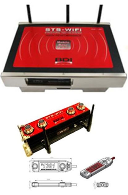
Wireless Structural Testing Systems The system consists of a main processing unit that samples data, junction boxes, and strain transducers. The strain transducers are mounted to structural elements with clamps or bolted to epoxied tabs. Each sensor has a unique identification number and a microchip that allows it to be identified and located within the system. The sensor calibration factors are stored in the configuration files and applied automatically. The main advantage of the STS system is a random wiring capability. Sensors can be moved within the system and instantly identified independent of channel number. The STS system is programmed and controlled with a notebook computer and powered with standard AC power or 12VDC vehicle power. The strain transducers measure strain using a full Wheatstone bridge configuration. They are ruggedized within an aluminum case. Connection to the STS junction boxes is through an amphenol military grade connector with the embedded ID chip. A standard test procedure consists of installing the strain transducers to the structural members, connecting each sensor to a junction box, connecting each box in series with a master cable, and connecting the master cable to the main STS unit. The system is initialized and all sensors are balanced to zero. Each test is assigned an automatic file number and the test is initiated using a trigger button called the clicker. Once the test is completed the data is downloaded from the STS unit to the attached notebook computer. The STS data files contain basic test information such as date, time, duration, sensor ID numbers, and the stress data in ASCII text format. |
 |
|
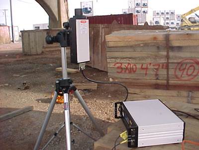
Laser Doppler Vibrometer The Laser Doppler Vibrometer (LDV), manufactured by Polytec PI, is a non-contact sensor that measures displacement and velocity of a remote point up to 200 meters away. The LDV uses laser interferometetry to measure vibration as opposed to simple signal time delay. A change in the distance between the laser head and the reflective target will produce a Doppler shift in the light frequency that is decoded into displacement and velocity. The system is composed of three parts: 1) the helium neon Class II laser head, 2) the decoder unit, and 3) the reflective target attached to the structure. The laser head is mounted to a tripod that is positioned underneath the target. The reflective target, typically retro-reflective tape, provides the strongest signal. The signal strength is read on a scale on the laser head. The tripod is adjusted to maximize the signal prior to a test run. Typically, the laser will take 5-10 minutes to relocate and iterate to a good position. |
 |
|
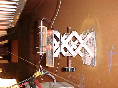
Linear Variable Differential Transformer An LVDT is to measure the deflection of the girder. Since LVDT is a contact sensor, a base or reference point was needed so that the LVDT arm would be compressed or extended as the bridge deflected. A stainless steel aircraft reference cable was used as the reference point. The stainless steel aircraft reference cable was mounted to the end diaphragms adjacent to the selected girder using angles. A 12-in. turnbuckle was used to tighten the cable to a proper tension. In addition, to account for creep and temperature effects on the cables, a spring was attached to one end of the cable to maintain proper tension. The LVDT was attached to the girder using a telescopic laboratory platform. The platform was mounted on the centerline of the web of the selected girder with high-strength epoxy. |
 |
|
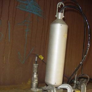
Geophone A geophone is a device which converts ground movement (displacement) into voltage, which may be recorded at a recording station. The deviation of this measured voltage from the base line is called the seismic response and is analyzed for structure of the earth. A geophone sensor, provided by Mark Products, Inc., is low-frequency three-directional geophone. |
 |
|
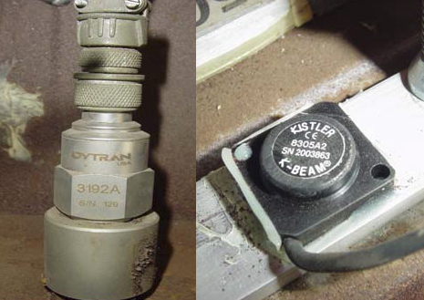
Accelerometer The purpose of using accelerometers is to indirectly measure the deflection of each girder under various test truck loadings. Accelerometer sensors, provided by Dytran Instruments, Inc., are relatively small—approximately 1 in. diameter and 2 in. tall—and are attached to the girders via a magnetic base. The accelerometers, manufactured by Kistler Instrument Corporation, use a three-layer silicon variable capacitance-sensing element capable of measuring low-level acceleration in a low-frequency environment (0–250 Hz). This characteristic becomes very important during signal processing of the recorded acceleration in predicting displacements. The accelerometers can be connected to the data acquisition system, MEGADAC, manufactured by Optim Electronics. |
 |
|
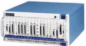
MegaDAC MEGADAC is equipped with input modules and offers up to 48 channels operating at speeds of up to 25,000 samples per second. The system program and test setup are done through Optim’s Test Control Software (TCS), which allows for, among other features, the formation of a user-defined sensor library and a real-time display of collected measurements. |
 |
|
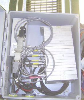
SoMAT The SoMat 2100 Field computer system is an ultra compact field data acquisition system. The main unit is composed of interchangeable modules called layers. Each layer serves a different function and layers may be added or removed depending on the type of monitoring. The unit can accommodate up to 20 channels and is powered by multiple 12VDC marine deep cycle batteries and a solar panel. Communication with the unit is done using a wireless link called FreeWave. The FreeWave radio transmitter allows complete control and data retrieval of the system within a range limited to two miles (line-of-sight). With four batteries the system can run unattended for up to three weeks. The SoMat FCS2100 is programmed using the Test Control Software provided by the manufacturer. The system is programmed to perform various operations called Data Modes. The mode is chosen to most efficiently capture the desired data. |
 |