Main menu
You are here
Advanced Concrete Material
Equipment
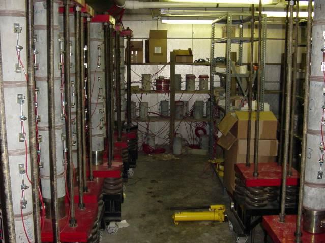
Environmental Chamber Shrinkage is very sensitive to its surrounding environment. Therefore the shrinkage specimens needed to be stored in an environmental chamber. The environmental chamber is a 24×16×8 ft room that has an insulated aluminum wall. A digital control unit located outside the chamber, controls the temperature and humidity of the room. The digital control unit acquires temperature and humidity readout from an environmental sensor inside the chamber. The sensor is positioned such that the overall temperature and humidity is at the set point. The range of temperature and humidity that the chamber could be set are between 39 – 104 degrees Fahrenheit and 40 – 70 percent, respectively. Inside the chamber, the temperature is adjusted through the heater and freezer units that are placed on one side of the wall. The unit is shielded with aluminum sheets and has blowers to help circulate the air in the chamber. The humidity is controlled by means of a steam generator that is located underneath the blowers. Dehumidification is achieved using an air conditioning unit to dry the air. |
 |
|
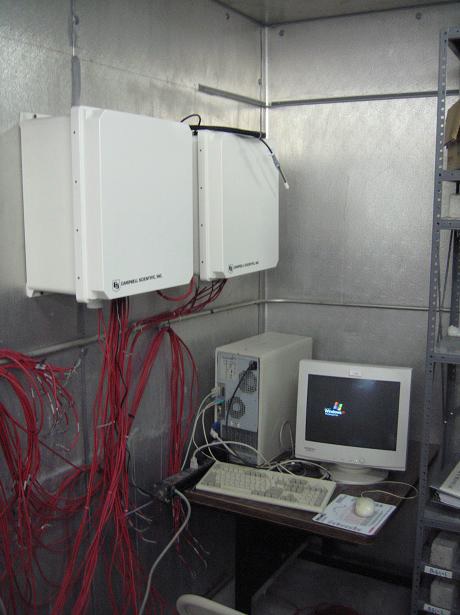
Data Acquisition System A data acquisition system (DAS), manufactured by the Campbell Scientific, Inc., was used in the data collection. The DAS is installed permanently into the environmental chamber. It is equipped with strain gage modules with the capability of monitoring 12 rings simultaneously. For the specified mixes, the DAS was programmed to collect data at 5- minutes intervals and download data daily to a permanent computer every 24 hours. |
 |
|
Beam Testing Frame "Big Red" The beam testing frame, also known as "Big Red", can hold beams up to 10 or 12 feet span and columns up to 8 feet in height. The capacity of the frame can be achieved up to 100k. |
 |
|
Sieve Shaker The sieve shaker is designed for shaking up to ten sieves and 2 1/8in high pan. Circular motion with an alternating up and down bumping action is designed to provide thorough repeatable sieving. |
 |
|
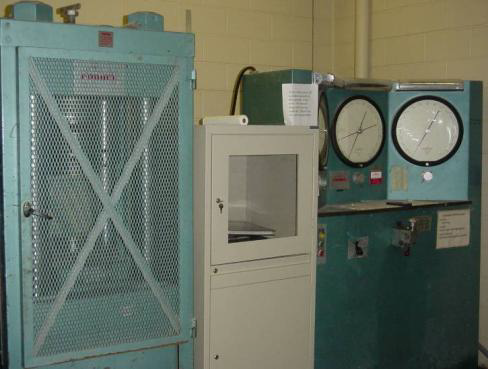
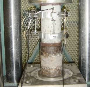
Forney 1-mil.lbs. Compressor Machine Compression Test The compression test is performed in accordance with ASTM C39 using the Forney 1 million pound compression machine. The machine is equipped with three dial indicators for different loading ranges. In addition to the dial indicators, a 500-kip digital load cell is used to automatically collect the data through a computer-based data acquisition system. Modulus of Elasticity Test The elastic modulus is measured in accordance with ASTM C469 using a compressometer. The compressometer is equipped with a digital dial gage that has an accuracy of 0.0005 inches. In order to minimize human error in reading the dial gage, a load cell, three high-precision LVDT’s, and an embedded strain gage were used as an alternative to the compressometer. This unit has been successfully used in the HPC study and has been proven to be more accurate than dial gages. Figure 4 shows the setup for the modulus of elasticity test. |
  |
|
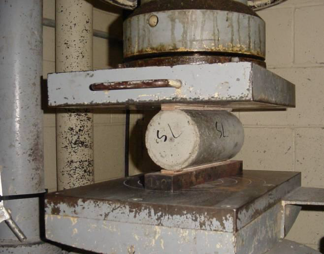
Tinius Olsen 400k Compressor Machine Tension Test Splitting tensile strength is determined by splitting a 4 X 8 in. cylinder in accordance with ASTM C496 using the 400-kip Tinius Olsen compression machine. The Tinius Olsen compression machine is used because it has a longer head extension than the Forney 1 million pound compression machine. In order to automate and minimize human error, a 250-kip digital load cell was also used in this test. |
 |
|
Other Equipment |
||
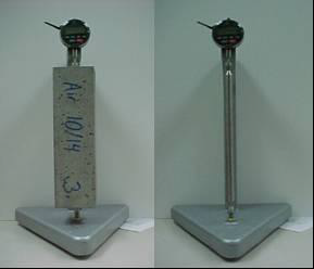
Free Shrinkage Test The test is done in accordance with ASTM C157. Three 3x3x10-in. prism concrete specimens were cast with gage studs placed at each end. The length between the two gage studs was measured in addition to the length of the reference bar using a length comparator. When using the comparator, the specimen is slowly rotated to record the minimum reading. Length change at various ages is recorded. |
 |
|
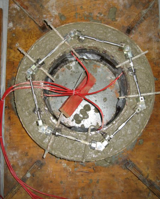
Restrained Shrinkage Test To measure the restrained shrinkage, concrete is cast around a steel ring in accordance with the test method of AASHTO PP34. The steel ring has an inner diameter of 11 in., an outer diameter of 12 in., and a height of 6 inches. The concrete wall thickness is 3 inches. The concrete is cast around the steel ring, such that as the concrete shrinks, a compressive stress is developed in the steel ring and balanced by the tensile stress in the concrete ring. If this tensile stress is greater than the allowable tensile stress of the concrete, it cracks. The cracks in the ring are monitored daily using a crack microscope. In addition, four foil strain gages (FSG) are instrumented at the mid-height of the inner surface of the steel ring so that abrupt changes in the steel strain can signal the age of cracking. The strain readings are recorded using a data acquisition system. |
 |